34 EUR
Download NowSold by thetechman on Tradebit
The world's largest download marketplace
3,308,366 satisfied buyers
The world's largest download marketplace
3,308,366 satisfied buyers

ROHDE & SCHWARZ Polyskop II SWOB BN4245
100.5226...
(BN 4245/..)
Edition R 31412 (Zusammengestellt nach R 31411)
(service manual)
German and English language, 272 pages
Revisited old scan
text, images 300dpi bitmap tiff
schematics 300dpi grayscale tiff
lossless LZW tiff scans, lossless ZIP PDF compression, 28 MBytes
Seamless scans
Retouched and normalized, print ready (combine files).
Table of Contents:
1. Characteristics 7
1.1 Uses 7
1.2 Description 9
1.3 Specifications 10
1.3.1 Sweep Generator 10
1.3.2 Receiver 11
1.3.3 Display Section 12
1.3.4 General Data 13
1.3.5 Order Numbers 14
1.4 Accessories Supplied 14
1.5 Recommended Extras 14
2. Preparation for Use and Operating Instructions 15
2.1 Legend for Fig. 2-1 15
2.2 Preparation for Use 16
2.3 Operating Instructions 17
2.3.1 Checking the EMF 17
2.3.2 Measuring the Output Voltage Root 18
2.3.3 Measurement of the Short-circuit Frequency Response 18
2.3.4 Display of Two Voltage Variables 18
2.3.5 Accurate Sweep-width Adjustment 19
2.3.6 Applying an External Marker 19
2.3.7 Measuring with the RF Diode Probe 19
2.3.8 Investigations on Test Items with Built-in Rectifiers 20
2.3.9 Amplitude Measurements 20
2.4 Measurement Examples 21
2.4.1 Measurement on a Single Tuned Circuit 21
2.4.2 Measurements on Eandpass Filters(coefficient
of coupling and bandwidth) 22
2.4.3 Limiters and Discriminators 23
2.4.3.1 Limiters 23
2.4.3.2 Discriminators 24
2.4.3.3 Possible Measuring Errors 24
2.4.4 Filter Alignment 25
2.4.4.1 Filter Adjustment Against a Standard 26
2.4.4.2 Possible Measuring Errors 26
2.4.5 Measuring the Amplifier Stage Gain 27
2.4.6 Video and Distributed Amplifiers 27
2.4.7 Determining the Frequency of Active Two-terminal
Networks 27
2.4.7.1 Method of Measurement 27
2.4.7.2 Test Setup 28
2.4.8 Checking the Frequency Calibration on Receivers 29
2.4.9 Alignment of Television Receiver Components 29
2.4.10 Measurements on Multicouplers 30
2.4.11 Locating Bad Earthing Conditions 30
2.4.12 Measurements on Cables, Cable Connectors and
Terminations 31
2.4.12.1 Determination of the Characteristic Impedance Z0 32
2.4.12.2 Determining the Dielectric Constan 32
2.4.12.3 Determining Cable Attenuation 33
2.4.12.4 Determining the Homogeneity 34
2.4.12.5 Measuring with a Mismatched Cable 34
2.4.12.6 Determining the Phase Angle of the
Reflection Coefficient 37
2.4.12.7 Possible Measuring Errors 37
2.4.13 Sources of Error 38
3 Maintenance 41
3.1 Replacing and Cleaning the Graticule 41
3.2 Replacing the Damps 41
3.3 Adjusting the Display Position 41
4. Circuit Description 42
4.1 Signal Generator 42
4.1.1 Sweep Oscillators 42
4.1.2 Sweep Linearization 43
4.2 Display Section 47
4.3 Marker Generator 51
4.4 Power Supply 52
5 Maintenance 54
5.1 Required Measuring Equipment 54
5.2 Replacing the CRT 54
5.3 Replacing the Valves 54
5.4 Checking the Voltages 54
5.4.1 Adjusting the Regulated Anode Supply Voltage 55
5.4.2 Adjusting the Regulated Filament Voltage 55
5.4.3 Meting the Voltage Values 55
5.5 RF Oscillators 55
5.6 Setting the RP Output Voltage 56
5.7 Replacing the Measuring Diodes 56
5.7.1 Control Diode 56
5.7.2 Eout Diode and RF Input Measuring Heads 56
5.8 0-reference line Adjustment 56
5.9 Equal Display Amplitudes for Positive or
Negative Signals 57
5.10 Marker Generator 57
5.11 Adjusting the Display Width 58
5.12 Adjustment of the Sweep-width Linearity 58
Fig. 1-1 Simplified block diagram 59
Fig. 2-1 Front panel 60
Fig. 2-2 EMF measurement 61
Fig. 2-3 Bandwidth measurement on single-tuned circuits 61
Fig. 2-4 Measurement on bandpass filters 62
Fig. 2-5 Filter alignment 62
Fig. 2-6 Input impedance characteristic with non-terminated
cable 63
Fig. 2-7 Error of input impedance characteristic when
match-terminated 65
Fig. 2-8 Amplitude characteristic for determination of
reflection coefficient 64
Fig. 2-9 Transformation of terminating impedance to the input 64
Pig. 2-10 Determining the phase angle of the reflection
coefficient 65
Fig. 2-11 Frequency response of input impedance with excessively
short cable 65
Fig. 4-1 Relation between magnetizing current and frequency 66
Fig. 4-2 Magnetizing current characteristic with sweep width
overdriving 66
Fig. 4-3 Control amplifier and blanking 67
Fig. 5-1 Adjustment points 68
Fig. 5-2 Eout diode and diode detector 69
Fig. 5-3 Pulse forms 70
Standard Translations for Parts lists
Supplement to Standard Translations for Parts Lists 71
Parts Lists
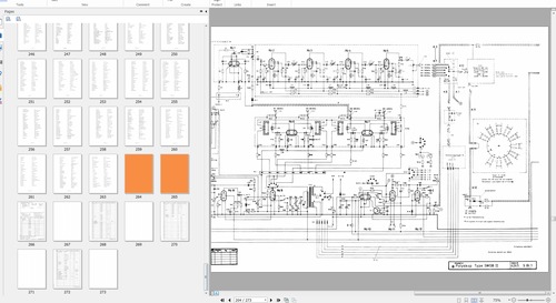
Drawings and Diagrams
File Data
This file is sold by thetechman, an independent seller on Tradebit.